| Schematic
Diagram Buy a kit or already made (no affiliation) |
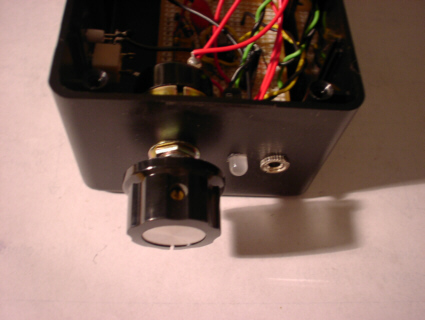 A total of five holes are drilled in the black plastic case. You may
want to purchase a drill bit set if you do not already possess one. A total of five holes are drilled in the black plastic case. You may
want to purchase a drill bit set if you do not already possess one. |
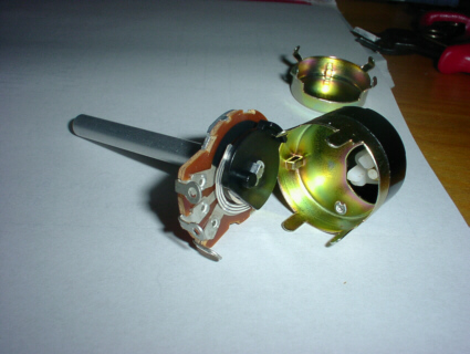 This is the "pot" with the original back in
the background, and is shown the switch, purchased separately that snaps in, carefully
with the black peg inserted between the two white pegs of the switch. This switch is
the new back, and the original metal back is thrown away. This is the "pot" with the original back in
the background, and is shown the switch, purchased separately that snaps in, carefully
with the black peg inserted between the two white pegs of the switch. This switch is
the new back, and the original metal back is thrown away. |
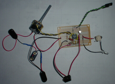 Here is shown the entire circuit, except the L.E.D. is not in the connector
in the top right corner, and the batteries are not snapped in. The shiny circle at the
upper right of the circuit board is the top end view of the electrolytic capacitor.
The black jack at the bottom is the lead connector for the electric pulse. The white
jack at the right side with a light bulb is the connector jack for the leads to the silver
wires. Here is shown the entire circuit, except the L.E.D. is not in the connector
in the top right corner, and the batteries are not snapped in. The shiny circle at the
upper right of the circuit board is the top end view of the electrolytic capacitor.
The black jack at the bottom is the lead connector for the electric pulse. The white
jack at the right side with a light bulb is the connector jack for the leads to the silver
wires. |
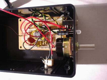 Here is a view with the parts mounted. The two parts that I glued in are the L.E.D. and
the light bulb. The L.E.D. connecter I scraped from an old junk p.c. (personal computer)
Here is a view with the parts mounted. The two parts that I glued in are the L.E.D. and
the light bulb. The L.E.D. connecter I scraped from an old junk p.c. (personal computer) |
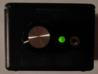 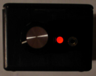 It was
tricky to get a photo of both states of the blinking L.E.D. but possible with a modern
digital camera on the multi exposure mode. Shown are the green and red states of the
bi-polar L.E.D. It was
tricky to get a photo of both states of the blinking L.E.D. but possible with a modern
digital camera on the multi exposure mode. Shown are the green and red states of the
bi-polar L.E.D. |
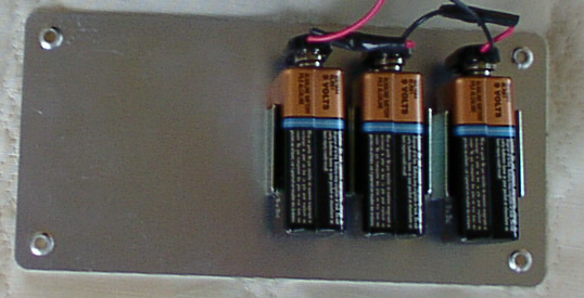 3
battery holders fastened to the metal lid cover of the case. This is mounted under
the black plastic cover, so both are screwed down on the case. 3
battery holders fastened to the metal lid cover of the case. This is mounted under
the black plastic cover, so both are screwed down on the case. |
| Pictures of the board full size | case | board 1 | board 2 | board 3 | board 4 | board 5 | |